What is the basic Network Topology?

Topology

Topology is a structure that connects computer systems or network devices. Physical, as well as logical aspects of a network, maybe described by topologies. Logical as well as physical topologies in the same network may be the same or different.

Point-to-Point

Point-to-point networks precisely include two hosts like a device, a switch, a router, or a server that has connected back to back by means of a single cable. Mostly, one host receiving end has linked to the other and vice versa.

Topology

Logically, the hosts may provide several intermediate devices when connecting point to point. However, the end hosts do not know the underlying network and see each other as if it were actually related.

Bus Topology

Both devices share a common transmission line or cable in the case of Bus topologies. The topologies of a bus can be difficult when several hosts simultaneously transmit data. Bus topologies then use either CSMA/CD or recognize one host as a bus master to resolve the issue. It is one of the basic networking methods in which a system malfunction does not damage other systems. But if the common communication line fails, all other devices will stop working.

Topology

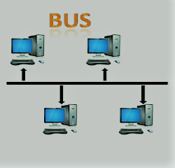
There is a line terminator on both ends of the shared channel. The information has sent in one direction only, and the terminator extracts the data from the line as soon as it hits the extreme end.

Star Topology

All-Star Topologies hosts have linked by point-to-point connectivity to a central node, called a hub device. Therefore, the connection between hosts and hub is points-to-point. There is a hub unit that can be:
Device with layer-1 like hub or repeater.
Kit for Layer 2 like a bridge or switch.
System layer 3 including gateway or router.

Topology

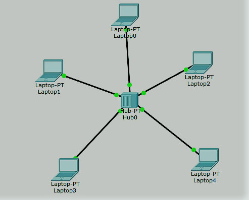
As is the case with bus topology, the hub functions as a single failure point. If the hub crashes, all hosts have not connected to all other hosts. Each contact between hosts has carried out only via the hub. Star topologies ies is not costly to connect to another host, only one cable is necessary and it’s simple to configure.

Ring Topology

Each host has connected to two other machines in ring topology to provide a circular networking system. If a host attempts to transmit or communicate a message to a non-next host, the data has sent to each intermediate host. The administrator can only require one additional cable if one host in the current structure has connected.

Each host loss causes the entire ring to collapse. Each bond in the ring is thus a point of failure. There are techniques that use an additional ring.
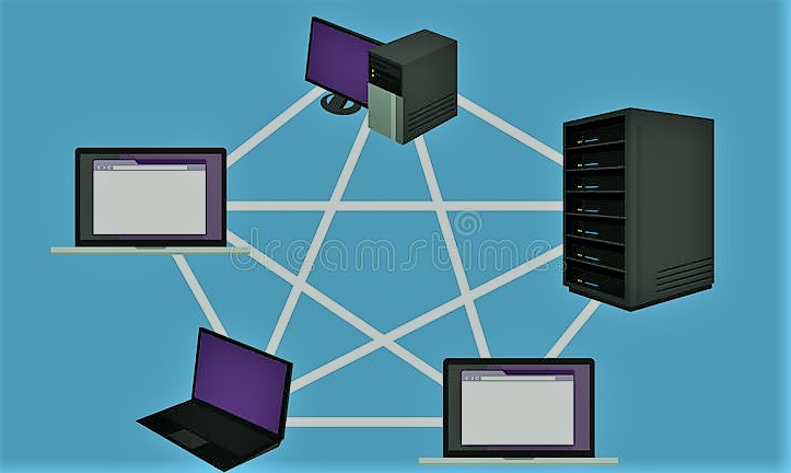
Mesh Topologies

A host has bound to one or more hosts in this form of topology. The topologies has hosts connected with all other host points or could have hosts connected with just a small number of hosts on a points-to-point basis.

In mesh, topology hosts have often used as a conduit for other hosts that have no point-to-point connections. Two styles of mesh technology:

Full Mesh: All hosts have connected point-to-point to all other network hosts. This requires connections n(n-1)/2 for each new host. It is among all network topologies the most stable framework.
Partially Mesh: Not all hosts bind any single host from point to point. Hosts randomly bind to each other. There is this topology where certain hosts need to be reliable.

Tree Topologies

This is the most general type of net topology currently in use, also known as Hierarchical Topology. This topology imitates expanded Star topologies and possesses Bus topologies properties.

This topology splits the network into many network tiers. The network has bifurcated into three network device types, especially in LANs. The lower part is a network link layer. The middle layer has referred to as a diffusion layer that acts as a mediator between the top and the bottom layer. The highest layer, the centre layer of the tree from which all nodes bend, is the focal point of the network.

The relation between all adjacent hosts is point-by-point. Similar to the bus topologies, the whole network suffers if the root is down, even if it is not the only failure point. Each link has seen as a fault, and failure splits the network into an unattainable section.

Hybrid Topology

Hybrid topology has said to be a network system. That has many topologies in its architecture. Hybrid topology is the legacy and demerit of all the topologies.

The image above describes a hybrid topology randomly. The combined topologies can be Star, Ring, Bus, and Daisy topology attributes. Much of the WANs have linked via the topology of the dual ring, with Star-Topology networks mostly connected. The Internet is the most extensive example of hybrid topology.

What is the basic operation of Zener Diode

Operation of Zener Diode

Zener Diode Perhaps the reverse voltage rises very quickly in the reverse current of a PN junction. This occurs as electrons have accelerated by the electrical field at the junction to high speeds and generate more free electrons by ionization of atoms. The field, therefore, speeds up these electrons, which induces further ionization. The mechanism of the avalanche leads to a huge current and the intersection has said to have broken down.

However, the disintegration is not harmful until the dissipation of power increases. The temperature to the degree where the local melting kills the semi-conductor. Over a broad spectrum of current, the voltage over the junction remains very stable. This effect has used to preserve the power supply output at the decommissioning voltage.

These PN junctions have referred to as the Zener diodes because of Clarence. Zener first proposed a reason for the sudden rise in current at collapse. Fig. 3-16 has a sharp transfer potential and a smooth current plateau above the breakdown. In the current-voltage curve of the Zener diode. Zener diodes can come from many milliamperes to several amperes with a decomposition voltage.

Figure 3-17 illustrates the way Zener diodes have used to regulate the output voltage of an electricity supply. The output voltage of the supplies shall not control exceed the diode’s zener-breakdown voltage. Then the potential increases to the potential for energy supply. If the load flow increases, the diode current decreases, so the reduction through Rs will still vary from the power supply voltage and the breakdown potential. The controlled output voltage remains constant at the diode breakdown potential, while the power-supply voltage changes under stress.

Zener Diode breakdown

The disintegration is either because of the effects of Zener under 5.5 V or because of ionization of the influence of more than 5.5 V. Both mechanisms lead to the same behavior and do not need any new circuitry, but the temperature coefficient of each mechanism is different.

The Zener impact has a low conductivity while the effect is positive. Both temperature effects are almost identical at 5,5 V and cancel each other such that the Zener diodes are the most stable under a large variety of environments at a rate of about 5,5 V.

Overvoltage protection

If the input voltage rises to a higher value than the Zener breakdown voltage, the current runs across the diode which causes a voltage drop through the resistor. The short circuit opens the fuse and separates the charge from the supply.

Clipping Circuits

AC waveform cutting circuits have used to alter or to form Zener diodes. The clipping circuit restricts or clips off portions of a waveform half or two cycles to shape the waveform.

Zener diode

Zener diode applications

Zener diodes are used as reference components, floating suppressors and in the device and cutting circuit switching for voltage control.

How is the Exclusive-OR Gate is the same as the addition?

Exclusive-OR Gate 

Exclusive-OR Gate by combining regular logic ports together to form more complex gate functions. Which have extensively used when creating numerical logic, computer logic, and error detection systems. We may achieve the Exclusive-OR Gate function or Ex-OR for short.

The two-input “Exclusive-OR” gate is primarily a two-adder module as it gives the sum of two binary numbers which makes the architecture more complicated than other simple logic gate forms. The following is the true table, logical symbol and application of an Exclusive-OR 2-input gate.

The output of the exclusive or Gate

That has, if the two input terminals on the “DIFFERENT” have at the logic of one another, the output of the exclusive or door is only HIGH.

An amazing amount of “1’s” logic on the inputs provides the “1” logic at the output. These two inputs will have the boolean statement “1” or “0” at the logical stage. A.B + A.B = (A to B)

The Digital Logic “Exclusive-OR” Gate

Input Exclusive-OR Gate

Exclusive-OR Gate

Giving Boolean: Q = AB + AB Speech
The above true table indicates that the output of the ONLY exclusive-OR gate is “Strong,” whether the two terminals in the gate area in the logic “DIFFERENT.” Where these two inputs, the A and B are all at the “1” level of the logic or both at the “0” level, the output is a “0.” In other words, if there is a strange amount of 1 in the inputs, the output is “1.”

In computing logic circuits, it gives one the following boolean expression: This ability to equate two logic level and generate output values based on the input state is very useful for computers:
A.B + A.B = (A to B)

The logic feature of a 2-input Ex-OR has as follows: the output at Q has provided with “ORB but NOT Both.” Generally, where an ODD number 1 has input to Gate, if all numbers equal it, the output is “0,” an Ex-OR gate would only give an output value of the “1” logic.

Ex-OR is then referred to as “special” or modulo 2-sum (Mod-2-SUM) for over two inputs rather than an ex-or. This definition can be extended to include all of the inputs shown below for a 3-input Ex-OR gate.

How is the basic Binary Parallel & Decimal Adder

Binary Parallel & Decimal Adder

Binary Parallel & Decimal Adder individual complete adder adds two one-bit numbers and carries an input. However, a Parallel Adder is a digital circuit willing, in parallel, to locate the integer amount of two binary numbers that exceed one bit in length.

It consists of complete adders attached to a chain. Where the output has connected to the input of the next higher-order in the chain from each full adder. To execute the procedure a bit of parallel adder needs n complete suppliers. Therefore, two adders have required for the two-bit number, while four adders are necessary for the four-bit number. Parallel suppliers usually provide bring look ahead logic to ensure. The spread between subsequent adding stages does not limit the supplement tempo.

Parallel Adder & Decimal Adder

Working of parallel Adder

  1. The complete adder FA1 first, as seen in the diagram, adds A1 and B1 along with the C1 to produce the number S1 (the first bit of the output sum) and the C2 to be attached in the chain to the next adder.

2. Next, the complete adder FA2 uses the input bit C2 to add S2 (2nd bit of the output amount) with the input bits A2 and B2, and C3 with C3, which has attached again to a chain adder.

3. The operation continues until the last complete adder, FAn uses the carrying bit Cn to add the last bit of output to Cout with input An and Bn.

BCD represents binary decimal coded. We’ve got two 4-bit numbers A and B, suppose. The A and B values can be between 0(0000 in binary) and 9(1001 in binary), since we take decimal numbers into account.

Parallel Adder & Decimal Adder

If we do not consider the carry from the previous number, the output would vary from 0 to 18. However, if we take the carrying into account, the maximum production value is 19 (i.e. 9+9+1 = 19).
If we only add A and B, the binary amount will be sent. In this case we can use the BCD Adder to obtain the output in BCD form.

What is the Compactor of BCD and magnitude

Compactor of BCD and magnitude

The Compactor of BCD and magnitude have previously shown the T-type flip flops has used as separate counters. If we link multiple toggles flops in a chain, a digital counter has produced which stores or shows the number of times a sequence of counts are present.

Clocked T-type flops are the binary counter-part-by-two and asynchronous counters; for the next stage, the contribution of one counting stage provides the pulse clock. So there are two different performance statuses of a flip flop counter. We can build a split by 2N counter by adding more flip flop levels. But the issue is that it counts between 0000 and 1111 for 4-bit binary counters. It’s in the decimal between 0 and 15.

In order to create a digital counter that ranges from 1 to 10. Only binary numbers 0000 to 1001 need to count. That’s from 0 to 9 decimal places and luckily we can count circuits with an Asynchronous 74LS90 integrated circuit.

Decade Counter.

When applying a clock signal, digital counters count upward from zero to a predetermined count. Until the count has reached, reset the counter to zero and restart it.
At the count of nine, a ten-year clock counts and then returns to zero. The counter must, of course, have at least four flip flops within the chain to count up to a binary value of nine to reflect each decimal digit as seen.

Compactor of BCD and magnitude

There are then four twist counters, with 16 possible states and 10 of them, and we can count to 100 or 1,000 or whatever the final number we want if we link a set of counters together.

It has called the Limit, which counts that a clock should also count. A counter returning to n has called a modulo-n counter, e.g. a modulo-8 (MOD-8) or a modulo-16 (MOD-16) counter, etc., and the maximum range for an n-bits counter is from 0 to 2n-1.

However, as we saw in the Asynchronous Counter tutorial, a counter that resets after 10 counts from binary 0000 (decimo “0”) to 1001 (decimal “9”) with a divided-by-10 count sequence can be called a “binary-coded-decimal counter” or a MOD-10 counter, using at least 4 toggles, can be created.

BCD counter

It is called a BCD counter since, unlike a straight binary counter, its ten state sequences are BCD and do not have a normal pattern. Then a single BCD counter, like the 74LS90, counts from the decimal zero to the decimal nine and can register up to nine pulses. Note that based on an input control signal, a digital counter will count or count up or down.

Binary-coded-decimal coding is an 8421 code of four binary numbers. The designation 8421 refers to the four digits or bits of binary weight used. 23 = 8, 22 = 4, 21 = 2 and 20 = 1. For example. The key benefit of BCD coding is that it makes it easier to convert decimal and binary numbers.

How are the Parallel and serial transmission differences?

Parallel and serial transmission differences

Parallel and serial transmission differences

Parallel and serial transmission

The parallel and serial transmission are two types used for data transfers between laptops and computers. There are some similarities and variations. One of the main distinctions has that the data has transmitted little by little in serial transmission, while a byte (8 bits) or character has sent continuously in the parallel transmission.

The relation is that they have used for connecting and communicating with peripherals. In comparison, the parallel transmission is way, but it isn’t the way.

Serial Transmission Concept

Data are transmitted from one device to another in two directions in the serial transmission, where each bit is the pulse rate for a clock. At a time eight bits (usually called the parity bit) have exchanged, i.e. 0 and 1, each with a start and stop bit.

Serial data cables have used to relay data over a longer path. Data have however transmitted in the correct order in the serial transmission. It has made up of a 9-pin D-shaped cable which connects data in sequence.

Parallel and serial transmission differences

Two synchronous and asynchronous subclasses of Serial Transmission. An additional bit has also applied for each byte of asynchronous transmission such that the recipient has alerted to new data delivery. Typically, 0 will be the beginning bit and 1 will be the stop bit. No extra bit, instead of transmitting data in the form of frames that contain several bytes, has added in synchronous transmission.

Without the sending and receiving of hardware, the serial transmission method did not operate. The hardware used to transmit and receive data will convert the data to serial mode from the sequential mode of the system (used in the machine) (used in the wires).

Parallel Transmission Concept

Different bits have sent along with a single clock pulse during parallel transmission. This is easy to send since it uses multiple data transmission input/output lines.

In addition, it has benefits that it often complies with the underlying technology since internal parallel circuits have used by electronic networks such as the computer and networking hardware. That is why the parallel interface is a good addition to the existing hardware.

Parallel transmission systems make assembly and troubleshooting simpler due to their location in single physical wiring. A 25 pin port, with 17 lines of signal and 8 ground lines, has used for parallel transmission. There is a further division between 17 signal lines.

Parallel and serial transmission differences

4 handshaking lines that trigger,
Status lines for error reporting and reporting, and 8 for data transmission.

Main differences between transmission in Parallel and serial transmission

  1. The serial transmission uses a new route, while simultaneous transmission involves many routes, to connect and transmit data.

2. For long-distance communication, serial transmission has used. Parallel transfer for the shortest path has used against this.

3. In comparison with the parallel transmission, error and noise are the smallest serial. Because one bit accompanies another in serial transmission, several bits have sent together in parallel transmission.

4. The data are transmitted over several lines at parallel processing is easier. Conversely, data passes across a single wire in serial transmission.

5. The Sender will transmit the data and receive them. Serial communication is a total duplex. Parallel transmission, by comparison, has half duplex because the data have transmitted or received.

6. In a serial transmission system, specific types of converters have needed to transform data between the internal parallel and the serial form without such a transfer requirement in parallel transmission systems.

7. In contrast with the Parallel Transmission Cables, serial transmission cables are shorter, slower and cheaper.

8. Simple and efficient serial transmission. In the other hand, transmission in parallel is inefficient and complex.