Direct Memory Access
Direct Memory Access (DMA: Here you may find a typical DMA procedure. The primary CPU and DMA device’s interactions have described. DMA’s effects on the inner cache of the CPU have also discussed.
Interrupt Handling: Hardware interrupts management of the processor has detailed here.
We have already looked at reading and write buses in this series on hardware fundamentals. In this post, we are covering DMA and interrupt handling. Direct memory access. Knowledge of DMA and interrupt handling is useful in creating programs that directly interface IO devices (DMA-based serial port design pattern is a good example of such a device).
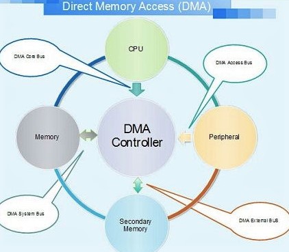
Direct Memory Access (DMA)
The processor bus request signal has asserted by a device that wants to execute DMA.
The processor ends the existing bus cycle and then reasserts the device’s signal for the bus grant.
Then the gadget sends the signal have received by the bus.
In the change in the status of bus awards, the processor perceives the ack signal and begins to hear data and DMA activity address bus.
The DMA device transfers the address from the source to the target.
The processor monitors addresses on the bus during such transfers and examines if any changed locations have cached in the processor during DMA operations. If a cached address on the bus has found by the CPU, one of two actions may has taken:
Processor invalidates the internal cache input for the DMA writes operation address.
When a DMA type has recognized, the processor changes an internal cache.
The unit will release the bus by reinforcing the bus release signal after the DMA procedures are complete.
The processor recognizes the release of the bus and continues its bus cycles from the point of departure.
Interrupt Handling
Here we explain the processing of interrupts in a case in which the hardware does not enable identifying the interrupting device. In certain circumstances, software must examine probable interfering devices.
The interrupt signal has asserted by a device at a hardwired interrupt level.
The processor records the interrupt and awaits completion of the current command.
Upon execution of the current instructions, the processor begins interruption by storing the current contents of the register on the stack.
Then the processor switches to supervisor mode and starts a break recognition cycle.
The address of the interrupt service procedure is the address of the vector (ISR).
The ISR monitors all devices to find the interrupting device. This has achieved by checking on devices that might have triggered the interrupt status registers.
The control has passed to the interrupting device-specific handler when the device has located.
The ISR performs the “return from interrupt” command once the device-specific ISR procedure has carried out its task.
Executing the “interrupt return” command results in processor status restored. The processor is back in user mode.
Interrupt Acknowledge Cycle
Here we explain interrupting management in a case where the device that caused the interrupt has identified by the hardware. In such instances, on the hardware level, the precise source of the interrupt has determined.
The interrupt signal has asserted by a device at a hardwired interrupt level.
The processor records the interrupt and awaits completion of the current command.
Upon execution of the current instructions, the processor begins interruption by storing the current contents of the register on the stack.
Then the processor switches to supervisor mode and starts a break recognition cycle.
The interrupter reacts with the vector number of the interrupt recognition cycle.
The vector number received above has used by the processor and fetches the vector.
The address of the interrupt service procedure (ISR) for the interrupting device is located on the vector.
The ISR performs the “return from interruption” command when the ISR has done its work.
Executing the “interrupt return” command results in processor status restored. The processor is back in user mode.
Synchronization Requirements for DMA and Interrupts
Software engineers often have to work with an interrupt or DMA-shared data structures. It demands that the shared important areas receive atomic updates.
Synchronization With Interrupts
When an ISR shares a data structure, deactivating the interrupt in order to update. The region of vital importance is a suitable method. Be aware that interrupt deactivation should only be limited to the code that updates the crucial area. The interrupt delay has increased by maintaining interrupts disabled for a lengthy time.
The usage of interrupts at instruction boundaries is also a further option. For atomic transactions, a single instruction that performs both reading and writing might be utilized. You may increase the shared semaphore without triggering interruptions, for instance, if your CPU allows a direct memory increase.
Synchronization With Direct Memory Access (DMA)
Data structures are hard to share with a DMA device. At the limit of a bus cycle, the CPU can start the DMA procedure. In the middle of an instruction, a new DMA operation can be initiated (Keep in mind that an instruction execution involves multiple bus cycles).
The optimal technique to update important regions is to employ the bus cycle for reading modification. This instruction enables atomic updates to be done in crucial locations. Where the reading and writing in a particular bus cycle have bonded together.
Another possibility is to deactivate the operation of DMA, and when using these techniques, extreme caution should be applied.
Certain processors enable the deactivation of DMA operations utilizing locked bus cycles. The CPU may perform a lock command for deactivating external bus permits, and when upgrades for important areas are finished, the instructions for unlocking the bus allowance are utilized.
Another technique for preventing DMA may be the temporary deactivation of the DMA device, and for example, deactivating the Ethernet controller will make certain that DMA operations are not initiated when an update is done in a critical area if the activities are handled by an Ethernet controller.