
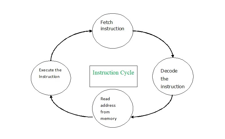
Instruction Cycle
There is a series of instructions for a program that resides in the memory unit of a computer. The CPU executes these instructions for each instruction across a cycle.
Each training cycle comprises the following steps on a basic computer:
- Fetch instruction from memory.
- Decode the instruction.
- Read the effective address from memory.
- Execute the instruction.
- Decode the instruction.
Input-Output Configuration
The input-output devices operate as an interface between the machine. The user in the computer architecture.
Input-Output Configuration
The input-output devices operate as an interface between the machine, and the user in the computer architecture.
An input device has to provide instructions. Data saved in the memory. The findings have shown via some output device to the user.
The figure below displays the arrangement of the input-output of a fundamental computer.
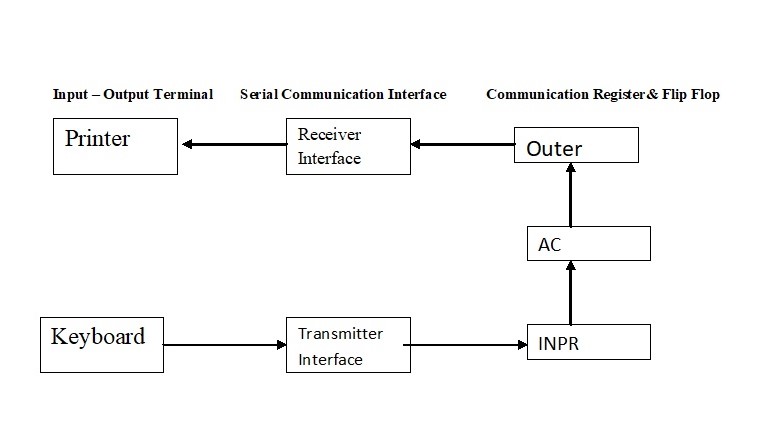
The terminals input and output send and receive information.
There have always eight bits alphanumeric codes for the quantity of information sent.
The keyboard information has changed to an ‘INPR’ input register.
The printer information has saved in the ‘OUTR’ output register.
The INPR and OUTR registers interact serially and with the AC in parallel through a communication interface.
The interface of the transmitter receives and sends information from the keys to INPR.
The receiver interface has sent from OUTR to the printer on a serial basis.
Design of a Basic Computer of Instruction Cycle
A basic computer consists of the following hardware components.
A 4,096 words 16 bits memory unit each
The registers: AC (Accumulator), DR (Data Register), AR (Data Register), IR (Instructions Register), PC (Program counter). TR, SC (Sequence Counter) (Output register).
I, S, E, R, IEN, FGI and FGO Flip-Flops
Two decoders: the decoder for 3 x 8 and the time decoder 4 x 16
The Control Logic Gates 16-bit common bus
Circuits Logic and Adder linked to the AC input.